
It should be noted that ATtiny is not supported by Arduino IDE out of the box. pinMode(led1, OUTPUT) // Works if this led1 setup is after pinMode(potentiometer, INPUT) DDRB &= ~(1 << DDB2) // Alternative working setup for analog input A1 PinMode(led1, OUTPUT) // Doesn't work if this is before pinMode(potentiometer, INPUT) If port BP1 setup has been made using straight to register there is no problem in order.Īny other analog input port and digital port combination works correctly.

Wrong order causes PB1 to high impedance, low current, output. * It is important in which order pin configuration has been set. If order of pin configuration is changed everything is OK.ĭ3 PB3 2| |7 PB2 A1 Voltage measurement, potentiometer That happens if inside setup() analog input A1 (pin 7, PB2) is configured after digital output PB1. It seems that output has been configured to high impedance mode. LED connected to pin PB1 lights very dim when output is high. You can also post your technical queries on our Electronics Forum to get better insights.Simplified circuitry there is 2 LEDs and 1 analog input. If you have any questions, leave them in the comment section. This is how you can program the ATtiny85 Microcontroller Chip using Arduino IDE and Arduino Uno.
Attiny85 port registers code#
If the LED connected to Pin 0 of Attiny85 IC blinks, then the code is uploaded successfully. Now go back to Tools -> Board and select “Attiny25/45/85”, then select ATtiny85 under Tools > Processor. Now, go to File > Examples > Basicsand open the Blink example.Ĭhange the pin number there from LED_BUILTIN to 0.
Attiny85 port registers install#
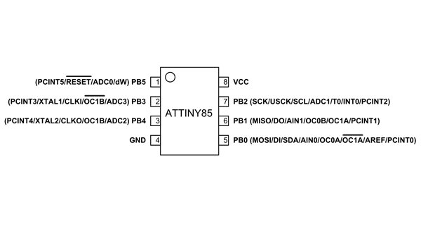
For that, go to File > Preferences and add the below link in the Additional Boards Manager URLs and click ‘OK.’Īfter that, go to Tools > Board > Board Manager and search for ‘attiny’ and install the latest version.Īfter installing it, now you would be able to see a new entry in the Board menu titled 'Attiny25/45/85'. To program the ATtiny85 with Arduino IDE, first, we need to add the ATtiny85 Support to Arduino IDE. Step 3: Programming ATtiny85 Using Arduino IDE: The complete connections are given in the table below: The positive pin of LED is connected to Pin 0 of the ATtiny85 IC through a 220Ω resistor while the GND pin is connected to the GND of IC. The complete schematic for Programming ATtiny85 with Arduino Uno is given below: Step 2: Circuit Diagram for Programming ATtiny85: After that, navigate to File > Example > ArduinoISPand upload the Arduino ISP code. For that, connect the Arduino Uno to Laptop and open the Arduino IDE. So to program the ATtiny85, we need to first configure Arduino Uno as ISP to act as a programmer for the ATtiny85. Since ATtiny85 is just a microcontroller, it requires an ISP (In-System Programming) to be programmed. Step 1: Configuring Arduino Uno as an ISP: OC1A: Timer/Counter1 Compare Match A Output OC0B: Timer/Counter0 Compare Match B Output MISO: SPI Master Data Input / Slave Data Output OC0A: Timer/Counter0 Compare Match A output MOSI: SPI Master Data Output / Slave Data Input OC1B: Timer/Counter1 Compare Match B Output Check out the table given below to know about the ATtiny85 pin description for each pin.

Most of the I/O pins of the chip have more than one function.
Attiny85 port registers software#
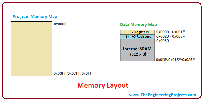
This microcontroller chip features 8KB ISP flash memory, 512B EEPROM, 512-Byte SRAM, 6 general-purpose I/O lines, 32 general purpose working registers, one 8-bit timer/counter with compare modes, one 8-bit high-speed timer/counter, USI, internal and external Interrupts, 4-channel 10-bit A/D converter, programmable watchdog timer with internal oscillator, three software selectable power saving modes, and debugWIRE for on-chip debugging. ATtiny85 Microcontroller Chip - IntroductionĪtmel's ATtiny85 is a high performance, low power 8-bit microcontroller based on Advanced RISC Architecture.


 0 kommentar(er)
